Wire tension in continuous flat wire rolling affects material movement, process stability, and the consistency of finished copper or aluminum flat wire. Changes in one section can influence the others.
Reliable tension management therefore requires coordinated feeding, rolling, and winding—not simply increasing or decreasing one motor’s speed. This guide covers tension variation, control methods, calculations, and equipment selection.
1. Why Wire Tension Matters
Wire tension is the longitudinal pulling force on moving material. It changes with unwinding resistance, material flow, drives, and winding conditions.
Poorly controlled tension can contribute to:
- Dimensional variation: Changes in longitudinal force may affect deformation and final wire dimensions.
- Tracking problems: Fluctuating tension can aggravate misalignment, particularly when wire guides are incorrectly set.
- Surface damage: Unstable wire movement may increase unintended contact with guides or machine components.
- Breakage or stoppages: Excessive loading or sudden changes can interrupt production.
Tension alone does not determine wire quality. Roll geometry, roll-gap settings, material consistency, lubrication, and alignment must also be controlled. For background on the forming process, see our Copper Rolling Process Guide.
2. Where Tension Changes Along the Line
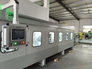
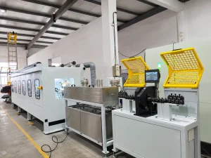
A continuous flat wire rolling line may include a payoff, guiding devices, one or more rolling stands, optional tension-control components, and a take-up system. Each section has different control requirements.
| Section | Control objective | Common influences |
|---|---|---|
| Payoff | Feed wire consistently | Unwinding resistance, braking, acceleration |
| Stand entry | Maintain stable material entry | Incoming tension, guides, material condition |
| Between stands | Coordinate material flow | Reduction, speed matching, interstand tension |
| Stand exit | Transfer wire steadily | Exit speed, downstream pulling force |
| Take-up | Wind under controlled tension | Changing coil radius, torque, winding speed |

At the payoff, variations in braking force or coil unwinding resistance can disturb entry tension. At interstand sections, differences between material delivery and intake can create tension fluctuations. At the take-up, the growing coil radius changes the relationship between winding torque and wire tension.
Not every line requires the same sensors or control devices.
3. Common Wire Tension Control Methods
Dancer-Based Control
A dancer uses a movable roller assembly to accommodate changes in wire movement. Its position can provide feedback for adjusting the speed of connected drives. Depending on its design, the applied dancer force also helps establish tension.
The dancer must suit the wire and operating conditions; incorrect adjustment can introduce instability.
Load-Cell Measurement
A load cell can measure the force acting on a sensing roller. With suitable geometry and calibration, this signal can be used to estimate wire tension and support feedback control.
Accuracy depends on installation, wire wrap angle, calibration, and signal processing. These factors must be checked before relying on readings.
Speed Coordination and Closed-Loop Control
Rolling stands must handle compatible material flow, but equal motor speeds do not necessarily mean equal wire speeds. Cross-sectional reduction, lateral spreading, and roll slip affect the relationship.
Where specified, a control system may combine coordinated drive references with dancer-position or tension feedback. A PLC and drive controller can adjust speed or torque in response to deviations. Poor tuning can cause oscillation or delayed response.
These are general engineering methods, not a statement that every CRM rolling line includes all of them. For related equipment-planning considerations, see How to Specify a Flat Magnet Wire Production Line for Custom Dimensions.
4. Basic Calculations for Tension and Material Flow
Tension and Tensile Stress
Average longitudinal tensile stress can be estimated using:
Tensile Stress (N/mm²) = Wire Tension (N) ÷ Cross-Sectional Area (mm²)
Rearranging:
Wire Tension (N) = Tensile Stress (N/mm²) × Cross-Sectional Area (mm²)
For an illustrative wire area of 4.5 mm² and an assumed tensile stress of 2 N/mm²:
Wire Tension = 2 × 4.5 = 9 N
This is a mathematical example, not a recommended tension setpoint or a guaranteed CRM equipment capability. Actual settings require engineering assessment of the material and process.
Matching Material Flow
Under ideal steady-state conditions, with negligible material loss and approximately constant density:
Input Area × Input Speed ≈ Output Area × Output Speed
If the input area is 6.0 mm², output area is 4.5 mm², and output speed is 20 m/min:
Input Speed ≈ (4.5 × 20) ÷ 6.0 = 15 m/min
These values illustrate theoretical material continuity; they are not recommended machine speeds or verified production performance. Actual roll rotational speeds and tension settings also depend on roll slip, material spreading, and operating conditions.
For another perspective on forming methods, see Flat Wire Rolling Mill vs Drawing Machine for Rectangular Copper Conductors.
5. Troubleshooting Unstable Wire Tension
Tension problems may originate away from where they become visible. Check the full wire path.
| Symptom | Possible causes | Checks |
|---|---|---|
| Repeated tension fluctuations | Payoff instability, drive mismatch, controller tuning | Payoff operation, speed feedback, control parameters |
| Excessive tension | High setpoint, excessive braking, take-up mismatch | Setpoints, brakes, drive response |
| Slack between stages | Speed or acceleration mismatch | Interstand material flow and synchronization |
| Winding tension changes | Increasing coil radius, inadequate compensation | Take-up torque and winding control |
| Tracking or surface problems | Guide misalignment, unstable wire path | Guide position, alignment, tension behavior |
A practical inspection sequence is to verify mechanical alignment and wire guides first; then check sensor calibration or dancer movement where fitted; review payoff, rolling, and take-up coordination; and finally assess the product under stable operating conditions.
Follow approved safety procedures, and avoid changing several parameters simultaneously.
6. What to Confirm Before Buying a Rolling Line
A supplier needs enough information to evaluate a suitable tension-control arrangement. Provide the material grade and condition, input shape and dimensions, finished width and thickness, tolerances, planned rolling stages, target capacity, and payoff/take-up requirements. Include surface and mechanical-property requirements.
Ask the supplier to describe the proposed tension-control method, measurement points if applicable, drive coordination, and operating limitations. Do not assume that a feature described in a general technical article is included in a particular machine quotation.
During agreed factory acceptance testing (FAT), evaluate finished dimensions, surface quality, stable operating speed, and accepted production output. Where tension control is included in the agreed equipment scope, verify its performance using the agreed test method. Guaranteed values should appear in the approved technical specifications.
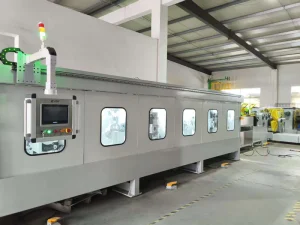
The CRM Precision Flat Wire Rolling Mill is a reference for discussing application-specific equipment configurations.
Frequently Asked Questions
Can rolling speed alone control wire tension?
Not in every configuration. Speed coordination is important, but effective control may also require mechanical regulation, dancer feedback, or direct tension measurement.
Is higher wire tension better for stability?
Not necessarily. Excessive tension increases tensile loading and can contribute to damage or breakage. Appropriate settings depend on the material and process.
Does every rolling stand need a tension sensor?
No. Sensor placement and quantity depend on the line architecture and selected control strategy.
Can tension control guarantee tighter tolerances?
No. Stable tension supports process consistency, but final tolerances also depend on roll geometry, gap control, incoming material, and other conditions.
Conclusion
Controlling wire tension in continuous flat wire rolling requires coordination across the payoff, rolling stages, and take-up. Dancers, load cells, and feedback control can be useful when correctly selected and integrated, but no single method suits every application.
Sky Bluer Environmental Technology Co., Ltd. (CRM) manufactures precision rolling mills and customized wire-processing equipment. Share your material specifications, conductor drawing, and target production capacity with our engineering team to discuss an appropriate line configuration.