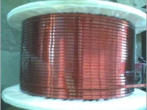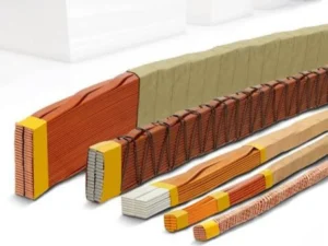
Choosing a flat wire rolling mill or drawing machine depends on incoming material, finished geometry, tolerances, and downstream use—not rated machine speed.
Rolling compresses copper between rotating rolls. Drawing pulls copper through a die. Both reshape metal through plastic deformation, but they control the final profile differently. For transformer and motor conductors, that distinction affects tooling, corner radius, surface quality, and stability.
Here is how to choose between them—or combine them.
Flat Wire Rolling Mill vs Drawing Machine: Key Differences
| Factor | Flat Wire Rolling Mill | Wire Drawing Machine |
|---|---|---|
| Forming mechanism | Compression between rotating rolls | Tensile pulling through a shaped die |
| Main tooling | Flat or profiled rolls | Round or profile drawing dies |
| Typical function | Flattening and rectangular profile formation | Diameter reduction or profile drawing |
| Thickness control | Roll gap, stiffness, reduction, tension | Die geometry, wear, material recovery |
| Width control | Lateral spread and edge-forming tools | Die opening and metal flow |
| Corner geometry | Profiled rolls or edge-rounding stage | Appropriately designed profile die |
| Primary risks | Uneven spread, misalignment, roll marks | Excessive drawing force, die wear, scoring |
| Changeover | Adjust or replace rolls and guides | Change dies and drawing sequence |
Neither process is inherently more precise; accuracy depends on the complete production setup.
How a Flat Wire Rolling Mill Works
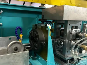
A precision rolling mill progressively reduces the thickness of round or preformed copper wire. As thickness decreases, the material elongates and may spread laterally. Roll geometry, reduction per pass, and entry/exit tension determine how consistently the target profile develops.
A typical route is:
Round Copper Wire → Initial Rolling → Intermediate Rolling → Edge Forming → Final Sizing → Inspection → Take-Up
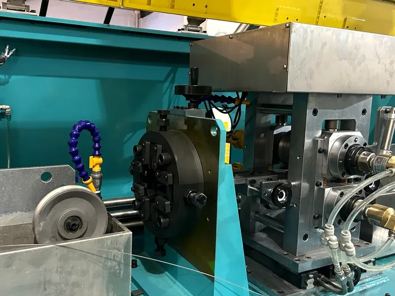
Roll Gap, Pass Schedule, and Edge Forming
In a conventional two-high (2-Hi) stand, adjusting the roll gap mainly changes thickness. Width is also affected by the amount of lateral spread; it cannot always be corrected by tightening the gap. Dedicated edge-forming rolls may be needed to achieve a specified corner radius.
Several moderate reductions can avoid the unstable width, asymmetric edges, or surface damage caused by an excessive single pass. The schedule must reflect material condition, geometry, and rolling force.
Guidance and drive synchronization matter: off-center entry can produce unequal corners despite acceptable thickness.
How a Drawing Machine Forms Copper Wire
A drawing machine pulls copper through a die whose opening is smaller than, or differently shaped from, the incoming section. Conventional drawing is widely used to reduce round-wire diameter before further processing. Rectangular production requires purpose-designed profile dies and a compatible pulling and guiding arrangement.
A possible route is:
Round Wire → Preliminary Drawing → Profile Drawing → Final Sizing → Inspection → Take-Up
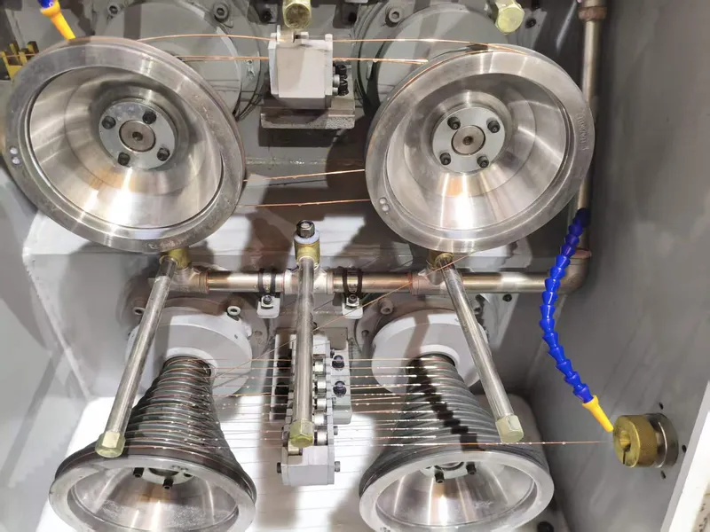
Die Geometry and Drawing Force
A profile die constrains more of the conductor perimeter than a flat rolling pass. However, the die opening does not automatically equal the final wire geometry: elastic recovery, incoming hardness, lubrication, and die wear also influence dimensions.
Excessive reduction increases drawing load, risking breakage, scoring, and die wear. Evaluate pulling force, permissible reductions, and profile geometry.
A standard round-wire drawing machine cannot produce precision rectangular wire simply by changing its speed settings. The tooling, wire path, and process design must support profile drawing.
Which Process Controls Dimensions and Corners Better?
Width and Thickness
Rolling offers direct mechanical adjustment of thickness through the roll gap, while width requires control of lateral flow and, where necessary, edge forming. In drawing, die geometry defines the intended profile, but tool wear and material recovery can shift the result.
Compare performance using the same material, dimensions, and inspection method. Request size-specific tolerance guarantees rather than generic “micron precision” claims.
Corner Radius and Surface Finish
Rectangular copper conductors need more than correct width and thickness. Sharp corners or burrs may damage enamel or insulation paper; excessive rounding reduces copper area within the specified outer dimensions.
Rolling may use a separate edge-rounding unit, whereas profile drawing relies on die geometry and the drawing sequence. Both processes require direct verification of the corner contour. A conventional width/thickness laser gauge does not, by itself, measure the complete corner radius.
Surface defects also differ: rolling can leave roll marks or damaged edges; drawing can produce die lines or scoring. Clean tooling, suitable lubrication, and controlled wire guidance are essential in either process.
For conductor geometry and quality requirements, see Bare Rectangular Copper Wire: Types, Applications and Manufacturing.
When to Combine Drawing and Rolling
For many electrical conductor lines, drawing and rolling perform different jobs. Drawing first establishes a consistent round-wire diameter; rolling then produces the rectangular section. Annealing may be introduced where necessary to obtain the required mechanical condition.
| Production Route | Best Considered When | Main Engineering Check |
|---|---|---|
| Drawing → Rolling | Copper rod or round wire needs diameter reduction before flattening | Drawing reduction and rolling pass schedule |
| Direct profile drawing | A defined rectangular profile can be produced through suitable dies | Die design, drawing force, and corner accuracy |
| Rolling → Profile sizing | Rolling forms the main shape but a sizing operation is proposed | Added cold work, die wear, and measurable benefit |
Integration adds tooling, maintenance, and control requirements. Choose the shortest process that meets the specification.
Copper Grade, Annealing, and Downstream Requirements
Electrical conductors commonly use Cu-ETP (C11000) or oxygen-free copper such as C10200. Both rolling and drawing introduce cold work, changing hardness and ductility. Variations in incoming material condition can affect forming loads and final geometry.
Annealing depends on accumulated deformation and required finished properties.
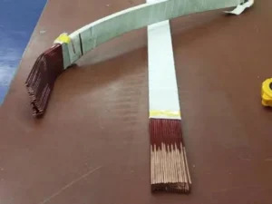
Downstream use is equally important. Transformer conductors need controlled geometry for winding and paper covering. Enameled wire requires a clean surface and suitable corner profile. Motor conductors that undergo bending or hairpin forming may have additional ductility requirements.
Specify bare and insulated conductor dimensions separately. For transformer applications, see Paper Covered Copper Flat Wire for Transformer Windings.
Equipment Selection: What to Specify
Before requesting a quotation, provide the supplier with a complete cross-sectional drawing and operating requirements:
- Copper grade, temper, and incoming wire diameter or profile
- Finished width, thickness, and tolerances
- Corner radius, edge condition, and surface requirements
- Required hardness or elongation and downstream insulation/forming steps
- Target production capacity, coil weight, and payoff/take-up format
- Available utilities, inspection requirements, and acceptance-test conditions
Request process flow, tooling, size-specific guarantees, and trial criteria. Design speed is not guaranteed speed at every conductor size.
Published CRM Rolling Mill Reference
The CRM Precision Flat Wire Rolling Mill for Transformers lists two 2-Hi rolling stands followed by an active edge-rounding mill, with tension control, cooling, dimensional measurement, and take-up.
| Published Parameter | Specification |
|---|---|
| Round-wire input | 1.0–6.0 mm |
| Finished width / thickness | 0.6–10 mm / 0.4–6 mm |
| Width / thickness tolerance | ±0.01 mm / ±0.005 mm |
| Adjustable corner radius | R0.05–1.0 mm |
| Design speed | 180 m/min |
These are published equipment specifications, not simultaneous guarantees for every material, size, radius, and operating speed. Confirm the achievable combination through technical evaluation or production trials.
Common Problems and Corrective Actions
| Symptom | Likely Cause to Investigate | Practical Response |
|---|---|---|
| Unequal corners | Off-center feed or misaligned tooling | Check centering and roll/die alignment |
| Thickness drift | Roll-gap movement or die wear | Inspect tooling and trend measurements |
| Surface scratches | Contaminated rolls, dies, or guides | Clean and inspect contact surfaces |
| Wire breakage | Excessive drawing load or unstable tension | Review reductions, lubrication, and material condition |
| Variable width | Unstable lateral spread or incoming material | Review rolling schedule and input consistency |
Avoid increasing rolling pressure or drawing tension indiscriminately; the adjustment may create a second defect without resolving the first.
Frequently Asked Questions
Is rolling always better for rectangular copper wire?
No. Rolling is well suited to progressive flattening and edge forming, while profile drawing can be effective for suitable geometries. Compare verified capability for the actual product drawing.
Can a standard drawing machine make rectangular wire?
Not without appropriate profile dies, pulling capacity, guidance, and a validated reduction sequence. Round-wire drawing capability alone is insufficient.
Which process gives a more accurate corner radius?
Either can achieve a specified radius with suitable tooling. The finished contour must be measured; width and thickness readings alone cannot confirm it.
Does the copper need annealing after forming?
That depends on initial temper, accumulated cold work, and required final hardness or elongation. Determine annealing from the complete production specification.
What should a supplier demonstrate before purchase?
Request representative samples or a trial showing finished dimensions, corner geometry, surface condition, stable operating speed, and consistency over a production length.
Conclusion
A flat wire rolling mill and a drawing machine are not interchangeable. Rolling forms rectangular sections through controlled compression; profile drawing uses shaped dies and pulling force. Many conductor lines use drawing for incoming diameter preparation and rolling for final geometry.
Sky Bluer Environmental Technology Co., Ltd. supplies CRM rolling and drawing equipment for copper and aluminum conductors. Share your copper grade, input dimensions, finished profile drawing, tolerances, corner radius, and production target so our engineering team can assess a suitable process configuration.