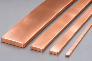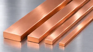
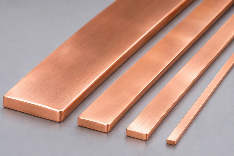
High-current direct-current (DC) systems depend on reliable conductors to transfer power between sources, converters, protection devices, and loads. Flat copper conductors are often selected because their rectangular geometry supports compact layouts, predictable contact surfaces, and flexible connection arrangements.
However, a flat shape does not automatically guarantee higher current capacity. Cross-sectional area, operating temperature, joint resistance, insulation clearance, and manufacturing quality all influence performance.
This guide explains the engineering considerations for flat copper conductors in high-current DC power systems and where precision flat wire rolling fits into conductor production.
1. Where Are Flat Copper Conductors Used?
Common applications include:
- Battery energy storage systems (BESS): DC links between battery racks, protection devices, and power conversion equipment.
- EV charging equipment: Internal DC distribution and connections between power modules.
- Solar and industrial DC distribution: Connections between converters, switchgear, and DC loads.
- UPS and backup power systems: Short, high-current connections in power conversion cabinets.
- Electric vehicle power electronics: Conductors connecting batteries, inverters, and distribution units.
Some installations use thick, rigid busbars cut from copper plate or strip. Others require narrower rectangular conductors, formed links, or flexible laminated assemblies.
These products do not all share the same manufacturing route.
2. Sizing a Flat Copper Conductor
Cross-Section, Resistance, and Losses
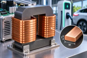
For a rectangular conductor of width W and thickness T, the nominal cross-sectional area is:
A = W × T
A conductor measuring 20.00 × 2.00 mm has a nominal area of 40.00 mm². Rounded edges reduce its actual metallic area slightly, so profile geometry matters when precise calculations or mass estimates are required.
The approximate resistance of a uniform conductor is:
R = ρ × L / A
Here, ρ is electrical resistivity, L is conductor length, and A is metallic cross-sectional area, using consistent SI units.
Using a copper resistivity of approximately 1.724 × 10⁻⁸ Ω·m at 20°C, a 0.8 m length with a 40 mm² section has an estimated resistance of 0.345 mΩ.
At 300 A, the calculated resistive loss is:
P = I²R ≈ 31.0 W
This is an illustrative calculation, not a permissible current rating. It excludes joints, cooling conditions, and temperature-dependent changes in resistivity.
Why Temperature Changes the Result
Copper resistance increases as temperature rises. For preliminary calculations near room temperature, an approximate temperature coefficient of 0.0039/°C is often used, but final values should follow the specified copper grade and applicable design standard.
Actual current capacity depends on allowable temperature rise, conductor orientation, enclosure ventilation, neighboring heat sources, and installation conditions.
A thermal assessment is necessary before selecting the final conductor section.
3. DC Operation Does Not Eliminate Connection Losses
In steady DC operation, the familiar AC skin-effect limitation is not the primary sizing concern. Nevertheless, contact resistance at bolted, welded, or clamped joints can create localized hot spots.
Joint performance depends on contact area, surface condition, fastening method, applied pressure, and environmental exposure.
Tin or nickel plating may be specified for certain connection systems, but the coating must suit the intended joining method and service conditions.
Ripple currents and switching transients from converters may introduce additional electrical effects. They should be assessed separately rather than treating a converter-fed DC link as perfectly steady DC.
For background on vehicle power conversion, see the U.S. Department of Energy’s power electronics overview.
4. Selecting Copper Grade and Material Condition
| Copper Grade | Designation | Typical Consideration |
|---|---|---|
| C11000 | Cu-ETP | High conductivity for general electrical conductors |
| C10200 | Cu-OF | Oxygen-free copper for specified processing requirements |
| C10100 | Cu-OFE | High-purity oxygen-free copper for demanding material specifications |
Material selection should consider conductivity, applicable standards, availability, joining processes, and required mechanical properties.
The Copper Development Association alloy database provides useful grade information.
Temper matters as much as grade. Soft copper is generally easier to bend; cold-worked copper may offer greater strength but less ductility.
Specify whether the conductor will be bent, punched, or welded after it is supplied.
5. Manufacturing Routes for Flat Copper Conductors
Large, thick busbars are commonly produced from copper strip, plate, or extruded stock. Smaller rectangular conductor sizes may be produced from copper rod or round wire through drawing and multi-pass rolling.
A representative wire-based route is:
Copper Rod/Round Wire → Drawing (if Needed) → Multi-Pass Rolling → Edge Finishing → Cleaning/Annealing (as Required) → Cutting/Forming → Coating/Insulation (if Required) → Inspection
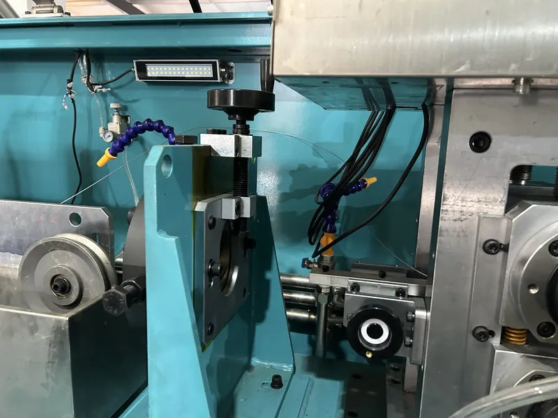
What a Precision Rolling Mill Controls
A precision flat wire rolling mill can manufacture bare flat copper conductor stock when the input material, target dimensions, and reduction schedule are within its engineered range.
Important process variables include:
- Roll gap: Controls thickness reduction and dimensional repeatability.
- Pass schedule: Distributes deformation to manage work hardening and edge formation.
- Wire guidance: Reduces lateral movement and alignment errors.
- Interstand tension: Supports stable material transport.
- Roll finish and cleanliness: Influence surface marks and scratch risk.
Reducing thickness can cause lateral spreading, so finished width and thickness must be controlled together.
Rolling is not a substitute for downstream punching, bending, plating, insulation, or electrical assembly.
For a comparison of forming methods, read Flat Wire Rolling Mill vs Drawing Machine for Rectangular Copper Conductors.
6. Specifications to Provide Before Equipment Selection
| Parameter | Information to Confirm |
|---|---|
| Copper material | Grade, temper, and conductivity requirement |
| Input stock | Round or rectangular shape, dimensions, surface condition |
| Finished size | Width × thickness, profile, and length |
| Dimensional quality | Width/thickness tolerances, straightness, flatness |
| Edges and surface | Corner radius, burr limits, scratch criteria |
| Downstream operations | Bending, punching, joining, plating, insulation |
| Output target | kg/h or tons/month; coil or cut-length delivery |
Drawings should distinguish the rolled conductor section from holes, bends, terminals, and other features made later.
Specify measurable acceptance criteria rather than requesting “maximum precision” without tolerances.
For insulation-related surface preparation, see How to Prepare Copper Flat Wire for Enameling and Paper Insulation.
7. Quality Control and Troubleshooting
Incoming copper should be checked for grade, dimensions, and visible defects. During rolling, monitor width, thickness, edge geometry, surface condition, and process stability.
Mechanical-property checks may be needed when subsequent forming is planned.
Completed DC assemblies can require joint-resistance measurement, dielectric verification, and temperature-rise testing.
Those assembly-level tests are separate from the acceptance criteria for bare rolled conductor stock.
Common Problems and Corrective Actions
| Problem | Possible Cause | Practical Check |
|---|---|---|
| Thickness drift | Roll-gap or thermal instability | Verify roll setting and operating conditions |
| Width variation | Uncontrolled lateral spread | Review reduction per pass and wire guidance |
| Edge cracking | Excessive deformation or unsuitable temper | Review pass schedule and annealing |
| Surface scratches | Tooling damage or handling contact | Inspect rolls, guides, and transport surfaces |
| Hot joints | Excessive contact resistance | Review joint design and assembly |
| Insulation damage | Burrs or sharp corners | Improve edge finishing and inspection |
8. Frequently Asked Questions
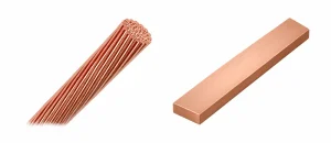
Are Flat Copper Conductors Always Better Than Round Cables?
No. Flat geometry can simplify packaging and provide broad connection surfaces, but cable flexibility, routing, vibration, insulation, and installation requirements may favor round or stranded conductors.
Does a Wider Conductor Automatically Carry More Current?
Not necessarily. Width increases area only if thickness is unchanged. Thermal conditions, connection design, and permissible temperature rise still determine whether a particular conductor is suitable.
Can a Wire Rolling Mill Make Complete DC Busbar Assemblies?
No. It can produce suitable bare rectangular stock within its designed capacity.
Cutting, forming, joining, coating, insulation, and electrical testing are separate operations.
Conclusion
Reliable flat copper conductors for high-current DC power systems require coordinated electrical sizing, thermal design, material selection, and manufacturing control.
Stable width, thickness, edge geometry, and surface condition are particularly important when rolled stock will undergo further fabrication.
Sky Bluer Environmental Technology Co., Ltd. manufactures precision rolling equipment for bare flat and rectangular metal conductors, not finished DC busbar assemblies.
Share your copper grade, incoming material, target width × thickness, tolerances, downstream operations, and production capacity so our engineering team can assess whether a rolling solution is appropriate.