Industrial electric motors rely on winding systems that can withstand electrical stress, thermal cycling, vibration, and continuous operation. Two common stator winding constructions are form-wound coils and random-wound coils. Although both convert electrical energy into a rotating magnetic field, their manufacturing methods, insulation systems, and typical applications differ significantly.
Choosing the right winding construction involves more than motor power or operating voltage. Engineers must consider insulation requirements, slot geometry, conductor dimensions, thermal performance, manufacturing costs, and long-term reliability.
This guide compares form-wound and random-wound coils, explains their manufacturing processes, and examines how precision rectangular copper conductors contribute to industrial motor production.
1. What Are Form-Wound Coils?
Form-wound coils are manufactured into a defined shape before being installed in the stator slots. Their geometry, coil pitch, and conductor arrangement are controlled during the forming process.
They are widely used in medium- and high-voltage motors, large industrial machines, and applications requiring robust insulation systems.
Key Characteristics of Form-Wound Coils
- Preformed geometry: Coils are shaped to match the stator design before insertion.
- Controlled conductor arrangement: Conductors occupy relatively well-defined positions within the coil.
- Engineered insulation: Turn insulation and groundwall insulation are designed for the required electrical stresses.
- Mechanical stability: Coil supports, bracing, and impregnation help withstand electromagnetic forces and vibration.
- Manufacturing precision: Conductor dimensions, bending geometry, and insulation thickness require careful control.
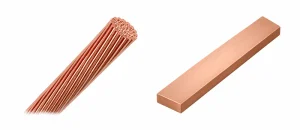
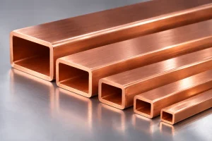
Form-wound coils frequently use rectangular copper conductors, although other conductor configurations are possible.
Rectangular conductors are particularly useful when the design requires controlled conductor placement and efficient utilization of available slot space.
2. What Are Random-Wound Coils?
Random-wound coils are commonly produced by winding insulated magnet wire directly into coils that are subsequently inserted into stator slots.
The individual conductors do not occupy precisely predetermined positions within the coil bundle, which distinguishes this construction from many form-wound designs.
Random-wound stators are widely used in low-voltage induction motors, pumps, fans, compressors, and general industrial equipment.
Key Characteristics of Random-Wound Coils
- Flexible winding arrangement: Individual wire positions are not strictly predetermined.
- Common use of round magnet wire: Enamel-insulated round copper wire is widely used.
- Automated production: Winding and insertion operations can be highly automated.
- Lower manufacturing complexity: Typically economical for standardized low-voltage motors.
- Application-specific insulation: Turn insulation, slot liners, phase insulation, and impregnation are selected according to the motor design.
Random-wound construction does not mean that the winding process is uncontrolled. Wire tension, turn count, coil dimensions, insertion conditions, and insulation quality still require precise management.

3. Form-Wound vs Random-Wound Coils: Key Differences
| Comparison | Form-Wound Coils | Random-Wound Coils |
|---|---|---|
| Coil construction | Preformed to a defined geometry | Wound into coil groups with less precisely positioned individual turns |
| Typical conductor | Often rectangular copper wire | Commonly round enamelled copper wire |
| Typical applications | Medium/high-voltage and large industrial motors | Low-voltage and general-purpose motors |
| Conductor positioning | Relatively controlled | Individual wire positions are less defined |
| Insulation design | Often includes substantial turn and groundwall insulation | Commonly uses magnet-wire enamel with slot and phase insulation |
| Manufacturing | Forming, insulation, insertion, and consolidation | Winding, insertion, insulation, and impregnation |
| Production cost | Generally higher | Generally lower for standardized designs |
| Repair considerations | Individual coils may be replaceable in suitable designs | Rewinding often involves replacing coil groups |
These are typical engineering differences rather than universal rules.
The winding type alone does not determine motor efficiency, insulation life, or maximum operating temperature. Those characteristics depend on the complete motor design.
4. Electrical Insulation and Voltage Requirements
Electrical insulation is one of the most important differences between the two winding constructions.
Form-Wound Coil Insulation
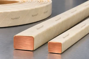
In medium- and high-voltage motors, form-wound coils often require carefully engineered insulation between turns and between the conductors and grounded stator core.
Depending on the design, the insulation system may include:
- Enamel or other conductor-level insulation
- Turn insulation
- Mica-based groundwall insulation
- Stress-control materials where required
- Resin impregnation or vacuum pressure impregnation (VPI)
The insulation system must be qualified for the intended voltage, thermal class, electrical stresses, and operating environment.
Random-Wound Coil Insulation
Random-wound motors commonly use enamel-insulated magnet wire together with slot liners, phase insulation, and impregnation materials.
For inverter-fed motors, repetitive voltage impulses and fast voltage rise times may create additional turn-to-turn insulation stress.
The insulation system must therefore be selected and evaluated for the actual power supply conditions.
Neither winding construction is automatically suitable for variable-frequency drive operation. Insulation qualification must reflect the electrical stresses expected in service.
5. Copper Conductor Geometry and Slot Utilization
The conductor cross-section influences electrical resistance, winding arrangement, and available space within the stator slot.
Round Copper Wire
Round conductors are flexible and well suited to automated winding operations.
However, gaps remain between adjacent circular conductors, and their arrangement can vary within a random-wound coil.
Rectangular Copper Wire
Rectangular conductors can be arranged in defined layers, potentially improving the utilization of available space.
However, the benefit depends on insulation thickness, corner geometry, conductor arrangement, and the complete slot design.
For example, consider a bare rectangular copper conductor measuring:
Width = 5.00 mm
Thickness = 2.00 mm
The nominal cross-sectional area, assuming sharp corners, is:
A = W × T = 5.00 × 2.00 = 10.00 mm²
If the conductor has rounded corners with a radius of 0.30 mm, the approximate copper area becomes:
A = W × T − (4 − π) × R²
A = 10.00 − (4 − π) × 0.30² ≈ 9.923 mm²
This difference matters when calculating conductor resistance and copper cross-sectional area.
Engineers must also account for insulation thickness and manufacturing clearances when calculating the actual slot fill factor.
A higher copper fill factor does not automatically guarantee better thermal performance. Heat transfer also depends on insulation materials, impregnation quality, cooling conditions, and winding construction.
6. Manufacturing Rectangular Copper Conductors for Form-Wound Coils
Many form-wound coil designs require rectangular copper conductors with controlled width, thickness, corner radius, and mechanical properties.
A possible upstream manufacturing process is:
Copper Rod or Round Wire → Drawing (if Required) → Multi-Pass Rolling → Edge Forming → Annealing (if Required) → Cleaning → Inspection
Precision Rolling and Dimensional Control
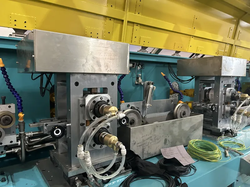
A precision flat wire rolling mill can transform round or preprocessed copper wire into the required rectangular profile.
Important process parameters include:
- Roll gap and reduction schedule
- Conductor width and thickness
- Corner radius and edge consistency
- Wire alignment and tension
- Surface finish and dimensional stability
Poorly controlled rolling may produce uneven edges, surface marks, or dimensional variations that affect subsequent insulation and coil forming.
For equipment details, see our precision flat wire rolling mill.
Surface Quality and Mechanical Properties
Copper conductors intended for insulation must be free from unacceptable burrs, scratches, embedded particles, and lubricant residues.
The conductor’s temper and ductility must also be compatible with the required coil-bending operations.
Depending on the material condition and accumulated cold work, annealing may be necessary.
For further information, read How to Prepare Copper Flat Wire for Enameling and Paper Insulation.
From Bare Copper to Finished Coils
After conductor preparation, separate manufacturing processes are required to apply insulation, form the coils, install them in the stator, and complete the insulation system.
A flat wire rolling mill manufactures the required bare copper profile; it does not independently produce finished form-wound motor coils.
For a comparison of upstream conductor-forming technologies, see our flat wire rolling mill vs drawing machine guide.
7. Quality Control and Common Manufacturing Problems
Reliable motor windings require inspection of both the copper conductor and the finished coil assembly.
| Inspection item | Main checks | Purpose |
|---|---|---|
| Copper material | Grade, conductivity, temper | Confirm conductor properties |
| Conductor dimensions | Width, thickness, corner radius | Maintain dimensional consistency |
| Surface condition | Scratches, burrs, contamination | Reduce insulation damage |
| Coil geometry | Shape, dimensions, conductor positioning | Support correct stator installation |
| Insulation system | Material, thickness, integrity | Verify electrical protection |
| Finished winding | Specified electrical and mechanical tests | Confirm compliance with design requirements |
Troubleshooting Matrix
| Problem | Possible cause | Recommended action |
|---|---|---|
| Form-wound coil does not fit the slot | Incorrect conductor dimensions, coil geometry, or insulation buildup | Verify drawings, forming dimensions, and insulation thickness |
| Insulation damage during bending | Sharp conductor edges, excessive bending strain, or unsuitable temper | Check corner radius, bending geometry, and material condition |
| Uneven conductor arrangement | Dimensional variation or unstable forming conditions | Improve conductor inspection and forming control |
| Electrical insulation test failure | Insulation defects, contamination, or processing variation | Inspect insulation materials, application, and test records |
| Excessive winding temperature | High losses, inadequate cooling, or poor thermal contact | Review electrical loading, cooling, and winding construction |
Acceptance limits should follow the motor manufacturer’s approved specifications and applicable standards.
8. How to Choose Between Form-Wound and Random-Wound Coils
The appropriate winding construction depends on the motor’s electrical, mechanical, thermal, and commercial requirements.
Important selection factors include:
- Operating voltage: Determine the insulation system required for the rated voltage and expected transient stresses.
- Motor size and slot design: Evaluate available slot space, conductor arrangement, and manufacturing feasibility.
- Operating conditions: Consider temperature, vibration, duty cycle, and environmental exposure.
- Power supply: Account for direct-on-line or inverter-fed operation.
- Production requirements: Compare tooling, automation, manufacturing complexity, and expected volume.
- Maintenance strategy: Consider inspection, repair, and replacement requirements over the motor’s service life.
Form-wound construction is often selected for large machines requiring precisely shaped coils and robust insulation systems.
Random-wound construction is generally attractive for standardized low-voltage motors where efficient, economical production is a priority.
The final choice should be based on the complete motor design rather than conductor shape alone.
Frequently Asked Questions
Are form-wound coils always made from rectangular copper wire?
No. Rectangular copper conductors are common in form-wound designs, but conductor selection depends on the motor’s electrical and mechanical requirements.
The defining feature is the controlled, preformed coil construction rather than the conductor cross-section alone.
Are form-wound coils more efficient than random-wound coils?
Not necessarily. Motor efficiency depends on winding resistance, electromagnetic design, core losses, cooling, and other factors.
Rectangular conductors may improve slot utilization in suitable designs, but this does not automatically result in higher motor efficiency.
Can random-wound motors operate with variable-frequency drives?
Yes, when their insulation systems are suitable for the expected inverter-generated voltage stresses.
The motor manufacturer’s specifications and applicable insulation requirements must be followed.
Why is corner radius important for rectangular motor winding wire?
Corner radius affects copper cross-sectional area, insulation application, and bending behavior.
Sharp edges can damage insulation, while excessive rounding reduces the available copper area within a fixed external profile.
Can a flat wire rolling mill manufacture complete form-wound coils?
No. A rolling mill produces the required bare rectangular copper conductor.
Conductor insulation, coil forming, stator insertion, impregnation, and final testing require additional manufacturing processes and equipment.
Conclusion
Form-wound and random-wound coils serve different requirements in industrial electric motors.
Form-wound coils offer controlled coil geometry and are widely used in demanding motor applications, particularly where engineered insulation systems are required. Random-wound coils provide flexible, economical manufacturing solutions for many low-voltage industrial motors.
For form-wound designs using rectangular copper conductors, accurate conductor dimensions, consistent corner geometry, suitable mechanical properties, and clean surfaces are essential to subsequent insulation and coil manufacturing.
Sky Bluer Environmental Technology Co., Ltd. (CRM) manufactures precision rolling mills and customized wire-forming equipment for solid rectangular copper conductors.
If your motor-winding project requires bare rectangular copper wire, share your copper grade, incoming material dimensions, target conductor width and thickness, tolerances, corner radius, and required production capacity.
Our engineering team can evaluate a suitable upstream rolling solution for your conductor manufacturing requirements.