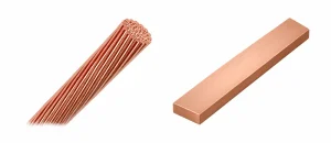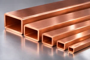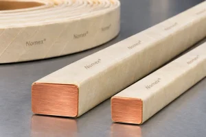
In high-frequency transformers, conductor selection involves more than copper cross-sectional area. As frequency rises, current distribution becomes uneven and winding losses can increase even when DC resistance appears acceptable. Litz wire and rectangular copper wire serve different needs; the right choice depends on frequency, current, winding geometry, insulation, and magnetic fields.
This guide compares both conductors, offers practical selection criteria, and explains how precision rolling supports rectangular copper conductor production.
1. What Is Litz Wire?
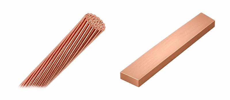
Litz wire combines individually insulated fine copper strands in a transposed bundle, helping distribute magnetic-field exposure and reduce certain high-frequency losses.
Where Litz Wire Works Well
Litz wire suits some high-frequency transformer and inductor windings where conventional solid conductors exhibit high AC resistance. It also offers flexibility during winding.
Performance depends on strand diameter, strand count, transposition pattern, operating frequency, and local magnetic fields.
Strand insulation and gaps reduce copper packing density, while stripping, soldering, and termination add manufacturing complexity. Poorly specified Litz wire may perform worse than expected.
2. What Is Rectangular Copper Wire?
Rectangular copper wire is a solid conductor with defined width, thickness, and corner radius. It may undergo insulation after forming or be supplied as an already insulated conductor.
Why Engineers Choose Rectangular Conductors
Rectangular geometry enables predictable winding layers, controlled positioning, and efficient use of the winding window. It can also simplify mechanical clamping and electrical connections.
However, thick solid conductors can develop substantial high-frequency losses.
Rectangular geometry alone does not eliminate skin effect or proximity effect.
Thin copper strip, foil, or multiple appropriately arranged parallel conductors may perform better than a single thick rectangular conductor, depending on magnetic-field orientation and winding layout.
3. Skin Effect and Proximity Effect: Key Design Considerations
Understanding Skin Depth
Skin effect concentrates alternating current toward the conductor surface, increasing effective resistance as frequency rises.
For copper near room temperature, a useful approximation is:
Skin depth, δ (mm) ≈ 66 / √f (Hz)
| Frequency | Approximate Copper Skin Depth |
|---|---|
| 20 kHz | 0.47 mm |
| 100 kHz | 0.21 mm |
| 500 kHz | 0.093 mm |
These values are reference estimates, not strict conductor thickness limits. Temperature, harmonics, and geometry also matter.
For example, a solid rectangular copper conductor measuring 5.00 × 2.00 mm should not be evaluated at 100 kHz using DC resistance alone.
Why Proximity Effect Matters
Magnetic fields from adjacent turns redistribute current inside conductors, producing additional AC losses.
In multilayer transformer windings, leakage flux, winding interleaving, layer count, and conductor orientation all influence proximity losses.
Fine insulated, transposed Litz strands can reduce certain losses but cannot eliminate winding-level proximity effects.
Likewise, thin rectangular conductors require careful electromagnetic design rather than simply selecting a thickness close to the calculated skin depth.
4. Litz Wire vs Rectangular Copper Wire: Engineering Comparison
| Design Factor | Litz Wire | Rectangular Copper Wire |
|---|---|---|
| High-frequency AC resistance | Can be low with suitable strand design | May increase significantly with unsuitable thickness or field orientation |
| Winding-window utilization | Strand insulation and gaps reduce copper packing density | Defined geometry supports orderly, compact winding layers |
| Mechanical handling | Flexible, but large bundles may be difficult to terminate | Dimensionally stable; bending requires appropriate material properties |
| Insulation | Individual strands insulated; additional winding insulation may be necessary | Requires an insulation system suited to voltage and construction |
| Manufacturing complexity | Strand insulation, bundling, transposition, and termination | Precision drawing or rolling, edge control, insulation, and winding |
| Typical selection priority | Reducing AC losses in suitable high-frequency applications | Controlled geometry, high-current connections, and repeatable winding construction |
The comparison should consider complete winding performance, including terminations, insulation, cooling, and manufacturing yield—not simply the copper price per kilogram.
5. How to Select the Right Conductor
Start with Electrical Requirements
Before selecting a conductor, establish:
- Switching frequency and significant harmonics
- RMS current and operating voltage
- Allowable winding temperature rise
- Number of turns and available winding-window dimensions
- Required insulation and cooling conditions
Copper losses can be estimated using:
Pcu ≈ I²Rac
Where:
- Pcu = AC copper loss (W)
- I = RMS current (A)
- Rac = effective AC winding resistance (Ω)
For non-sinusoidal current, individual harmonic contributions should be considered.
Compare candidate designs using calculated or simulated AC resistance, then validate promising configurations through prototype testing.
Consider Winding Geometry and Manufacturing
Litz wire is worth evaluating when fine strands and proper transposition provide meaningful AC-loss reduction.
Rectangular copper is worth evaluating when consistent layer geometry, mechanical stability, and high-current connections are priorities.
In some designs, thin copper foil or parallel conductors may outperform thick solid wire or bulky Litz bundles.
Engineers should also evaluate bend radius, insulation buildup, creepage distance, clearance, connections, and cooling paths.
A conductor that appears optimal electrically may still be difficult to manufacture consistently.
6. Manufacturing Rectangular Copper Wire for Transformer Windings
For solid rectangular copper conductors, a typical upstream production sequence is:
Copper Rod or Round Wire → Drawing (if Required) → Multi-Pass Rolling → Edge Forming → Annealing (if Required) → Cleaning → Dimensional Inspection
Precision Rolling and Dimensional Control
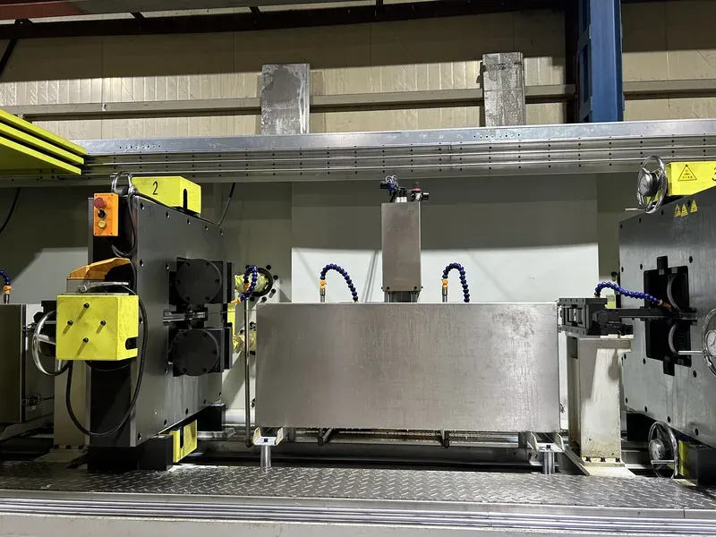
A precision flat wire rolling mill helps control conductor width, thickness, edge geometry, and surface condition.
Important process variables include:
- Roll-gap adjustment and reduction schedule
- Wire guidance and tension
- Width and thickness consistency
- Corner radius and edge profile
- Roll surface finish and lubrication
These factors affect dimensional repeatability and the suitability of the conductor for subsequent insulation processes.
Surface Quality and Corner Radius
Sharp edges may damage insulation during bending or winding. Excessive corner rounding, however, reduces the available copper cross-sectional area.
Surface scratches, burrs, embedded particles, and residual lubricants can also interfere with insulation application.
For more information, see How to Prepare Copper Flat Wire for Enameling and Paper Insulation.
A rolling mill manufactures the bare rectangular copper profile, not a complete insulated transformer winding or Litz wire bundle.
For a comparison of upstream conductor-forming technologies, read our Flat Wire Rolling Mill vs Drawing Machine guide.
7. Common Problems and Troubleshooting
| Problem | Possible Cause | Recommended Action |
|---|---|---|
| Excessive winding temperature | High AC resistance, proximity losses, inadequate cooling | Reassess frequency spectrum, conductor arrangement, and thermal design |
| Litz wire performs below expectations | Unsuitable strand diameter, poor transposition, termination losses | Review strand specification and measure winding AC resistance |
| Rectangular copper damages insulation | Sharp corners, burrs, excessive bending strain | Check corner radius, surface finish, and material temper |
| Poor winding-window fit | Excessive insulation buildup, dimensional errors, unrealistic packing assumptions | Verify insulated dimensions and test a prototype winding |
| Uneven current sharing between parallel conductors | Unequal impedances or unsuitable conductor arrangement | Review connection symmetry, magnetic-field exposure, and current distribution |
Manufacturing acceptance limits should follow the transformer designer’s approved specifications and applicable standards.
8. Frequently Asked Questions
Is Litz Wire Always Better at 100 kHz?
No. Its performance depends on strand construction, transposition, and magnetic-field distribution.
A properly designed thin-strip or foil winding may outperform an unsuitable Litz wire bundle.
Can Rectangular Copper Wire Be Used in High-Frequency Transformers?
Yes. Its suitability depends on conductor thickness, layer arrangement, field orientation, and acceptable AC losses.
A thick solid conductor should not be selected solely according to its DC current rating.
Does a Flat Wire Rolling Mill Produce Litz Wire?
No. Litz wire requires separate fine-strand insulation, twisting or transposition, and bundling processes.
Precision rolling equipment manufactures solid flat or rectangular copper profiles.
Conclusion
Selecting between Litz wire and rectangular copper wire requires balancing AC losses, winding geometry, insulation, thermal performance, and manufacturability.
Litz wire can reduce certain high-frequency losses through fine insulated strands, while rectangular copper offers controlled dimensions and repeatable winding geometry. Both require validation within the complete transformer design.
Sky Bluer Environmental Technology Co., Ltd. manufactures precision rolling equipment for solid rectangular copper conductors.
For an upstream copper conductor production project, share your copper grade, incoming material dimensions, target width × thickness, dimensional tolerances, corner radius, and required production capacity.
Our engineering team can evaluate a suitable precision rolling solution for your manufacturing requirements.