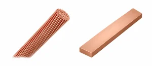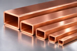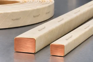
Edgewise wound flat wire coils use rectangular conductors bent around their narrow edges to form compact, repeatable windings. They are used in selected motors, inductors, reactors, and power-conversion equipment.
Edgewise winding is not a direct substitute for round-wire winding: bendability, insulation, dimensions, and electrical losses must be considered together. This guide explains the design principles, manufacturing sequence, common defects, and the role of precision flat wire rolling equipment.
1. What Is an Edgewise Wound Flat Wire Coil?
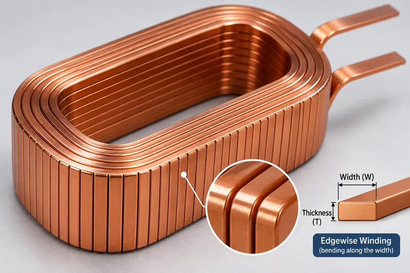
In edgewise winding, a rectangular conductor is bent in its width direction, with one narrow edge facing the inside of each turn. Its broad faces can be stacked along the coil axis, producing an orderly winding.
This differs from flatwise bending, where the conductor bends across its thickness. The methods require different tooling.
Edgewise coils may be circular, oval, or rectangular. Suitability depends on conductor dimensions, bend radius, and insulation.
2. Design Requirements for Edgewise Winding
Conductor Width, Thickness, and Bend Radius
Define the bare conductor width (W), thickness (T), corner radius (r), and minimum inside winding radius before specifying equipment. Width-to-thickness ratio influences forming behavior, but there is no universal safe bending radius.
During edgewise bending, the inner narrow edge experiences compression while the outer edge experiences tension. Excessive deformation may cause buckling, wrinkling, edge cracking, or distortion of the cross-section.
Bend trials should establish a practical minimum radius for the selected copper grade, temper, dimensions, and coating. One conductor’s limit may not suit another.
Electrical and Thermal Design
For a nominal 4.00 × 1.50 mm conductor, the rectangular area is 6.00 mm² before corner-radius correction. Actual area and resistance depend on profile and temperature.
At low frequency, conductor resistance is strongly related to copper area and total length. At higher frequencies, skin and proximity effects can increase AC losses. Edgewise geometry alone does not guarantee lower resistance or improved cooling.
Engineers should evaluate RMS current, harmonic content, winding temperature rise, turn spacing, insulation thickness, and cooling access using the complete electromagnetic design.
Insulation and Clearance
Most electrical coils require an appropriate insulated conductor or a validated insulation process. Edgewise forming can strain enamel or other coatings at the inner and outer bend regions.
Specify dielectric withstand requirements, turn-to-turn insulation, creepage and clearance distances, and the permitted coating damage criteria. Verify insulation after bending, not only on the incoming straight wire.
3. Manufacturing Process: From Flat Copper Wire to Finished Coil
A representative production route is:
Copper Rod or Round Wire → Drawing (if Required) → Multi-Pass Rolling → Edge Finishing → Annealing/Cleaning (as Required) → Insulation → Edgewise Winding → Coil Inspection
The sequence varies with material, coating, and winding method.
Preparing the Rectangular Conductor
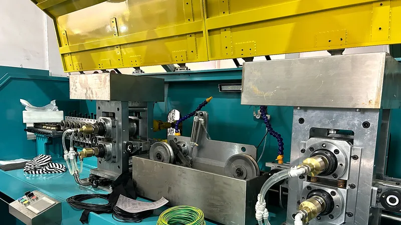
A precision flat wire rolling mill produces bare rectangular copper wire with controlled width, thickness, corner radius, and surface condition.
Key upstream controls include roll-gap settings, pass reductions, guidance, tension, lubrication, and roll finish. Poor dimensional consistency can cause unstable feeding or inconsistent coil pitch.
The conductor should be checked for burrs, scratches, embedded particles, and residual lubricant before insulation. See How to Prepare Copper Flat Wire for Enameling and Paper Insulation for related preparation considerations.
Edgewise Forming and Winding
Dedicated winding machinery guides the insulated flat wire, controls feed length or mandrel rotation, and bends the conductor around the intended coil profile. Some systems use progressive bending; others combine guided bending and continuous winding.
Tooling must support the broad faces to limit twisting, tilting, and local deformation. For rectangular coils, corner forming and springback compensation are especially important.
Control turn pitch, alignment, spacing, and lead position. Inspect the released coil because springback can alter its shape.
Inspection and Validation
Useful checks include conductor dimensions, coil inner and outer dimensions, turn count, pitch, terminal position, DC resistance, and insulation integrity.
For critical products, add dielectric, thermal, and mechanical tests under the approved specification.
4. Edgewise Winding vs Conventional Winding
| Factor | Edgewise Wound Flat Wire | Conventional Round-Wire Winding |
|---|---|---|
| Conductor geometry | Defined rectangular width and thickness | Circular cross-section |
| Packing arrangement | Can create orderly, stacked turns | Packing depends on wire diameter and winding pattern |
| Forming difficulty | Edgewise bending and springback require specialized control | Usually easier to bend at comparable conductor sizes |
| Insulation risk | Coating strain and edge contact require attention | Coating damage remains possible during winding |
| Electrical performance | Depends on geometry, frequency, and field distribution | Also depends on conductor size, frequency, and layout |
Neither method is universally superior; compare electrical, thermal, mechanical, and production requirements.
5. Typical Applications
Electric motors: Edgewise coils may be used in selected stator or field-winding designs requiring repeatable coil geometry and controlled conductor placement. They are not interchangeable with every hairpin or random-wound motor design.
Inductors and reactors: Compact, orderly windings can be useful in DC-link reactors, power-factor-correction circuits, and other magnetic components, subject to loss and temperature-rise verification.
Transformers and power conversion: Rectangular conductors can support repeatable winding construction, but high-frequency suitability requires AC-loss analysis. Thin foil, parallel conductors, or Litz wire may be preferable in some designs.
The application must determine the conductor specification.
6. Common Manufacturing Problems and Troubleshooting
| Problem | Likely Cause | Recommended Action |
|---|---|---|
| Wrinkles at inner edge | Excessive compression or insufficient support | Increase bend radius or revise forming tooling |
| Cracks at outer edge | Excessive tensile strain or unsuitable temper | Review material condition and validate bend limits |
| Damaged insulation | Sharp corners, surface defects, or severe bending | Improve edge finish and inspect coating after forming |
| Uneven turn spacing | Feed variation, twisting, or poor guidance | Check feeding synchronization and guide alignment |
| Coil shape changes after release | Springback or inadequate corner compensation | Adjust tooling and validate released dimensions |
A consistent incoming conductor reduces avoidable winding variation. For upstream process selection, compare the capabilities of a flat wire rolling mill and drawing machine.
7. Frequently Asked Questions
Can Any Flat Copper Wire Be Edgewise Wound?
No. Feasibility depends on width, thickness, temper, corner radius, coating, and minimum bend radius. Sample forming trials are advisable.
Does Edgewise Winding Automatically Improve Efficiency?
No. Compact winding geometry can be beneficial, but efficiency depends on AC/DC resistance, magnetic fields, insulation, cooling, and operating conditions.
Does a Flat Wire Rolling Mill Make Finished Edgewise Coils?
No. A rolling mill manufactures the bare rectangular conductor. Insulation and edgewise coil winding require separate, suitable equipment and process controls.
Conclusion
Successful edgewise wound flat wire coils begin with the correct conductor specification and continue through controlled bending, insulation verification, and finished-coil testing.
Sky Bluer Environmental Technology Co., Ltd. manufactures precision rolling equipment for bare rectangular copper conductors, not complete edgewise winding machines.
For an upstream conductor-production project, share your copper grade, incoming material size, target width × thickness, corner radius, dimensional tolerances, and required capacity. Our engineers can assess an appropriate flat wire rolling solution.