Distribution transformers must transfer electrical power efficiently while meeting limits for temperature rise, insulation performance, size, and short-circuit strength. The winding conductor is one of the decisions that affects these requirements. Two common approaches are copper foil windings and windings made from rectangular copper wire.
Both use copper, but they differ in conductor geometry, winding methods, insulation arrangement, and manufacturing requirements. Neither is automatically more efficient or more reliable. The appropriate choice depends on the transformer rating, voltage, current, cooling method, and overall design.
1. What Are Copper Foil Windings?
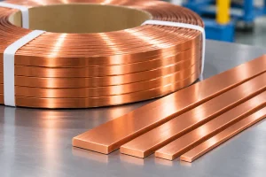
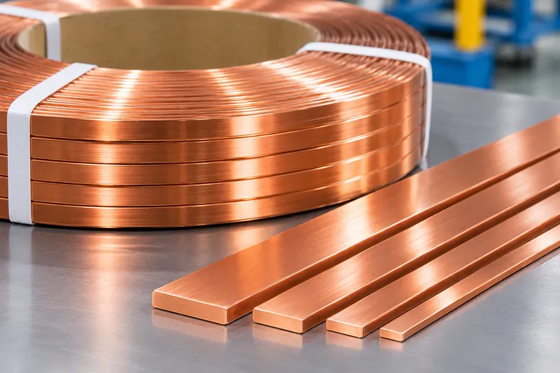
Copper foil windings use a continuous, relatively wide and thin copper strip wound around a core limb or winding former. Insulating material is placed between successive turns or layers to provide the required dielectric separation. In many designs, the foil width corresponds approximately to the axial height of the winding.
Foil construction is frequently used for low-voltage, high-current windings in distribution transformers. Its broad conductor cross-section can carry substantial current without requiring numerous separate parallel wires. However, the foil thickness, width, number of turns, and insulation system must be selected for the specific electrical and thermal requirements.
Manufacturing involves controlled strip feeding, tension, edge alignment, interturn insulation, and secure connections at the conductor ends. A winding made from foil is not necessarily simpler in every respect: handling wide strip and maintaining insulation integrity require dedicated process control.

2. What Are Rectangular Wire Windings?
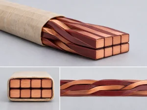
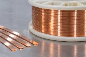
Rectangular wire windings use copper conductors with defined width, thickness, and corner geometry. Individual wires may be enamelled, paper-covered, or otherwise insulated according to the transformer design. They can be wound in layers or other specified arrangements, with one conductor or multiple parallel conductors.
Rectangular copper wire is used in different winding positions, including low-voltage and high-voltage applications where the electrical and mechanical design supports it. The conductor shape offers predictable dimensions and can support compact winding layouts.
For higher currents, parallel wires may be required. Their placement, transposition where applicable, and termination design influence current sharing and additional losses. Consistent wire dimensions and smooth edges are important for reliable insulation and winding operations.
3. Copper Foil vs Rectangular Wire: Key Differences
| Evaluation factor | Copper foil winding | Rectangular wire winding |
|---|---|---|
| Conductor form | Wide, relatively thin copper strip | Individual rectangular copper wires |
| Typical use | Often low-voltage, high-current windings | Low- or high-voltage windings, depending on design |
| Winding process | Wide-strip winding with insulation between turns | Winding of insulated wires, sometimes in parallel |
| Electrical losses | Depend on foil dimensions and leakage-field orientation | Depend on wire dimensions, arrangement, and parallel paths |
| Insulation | Interturn or interlayer insulation and specified barriers | Individual conductor insulation plus winding insulation |
| Production requirements | Strip quality, edge alignment, tension, and insulation placement | Wire geometry, edge quality, insulation, tension, and conductor arrangement |
| Cost considerations | Foil stock, winding equipment, insulation, and connections | Wire processing, insulation, parallel conductors, and winding labor |
These are general differences, not universal performance rankings. Transformer-specific calculations and manufacturing trials should determine the final choice.
4. Electrical Losses and Current Distribution
Copper losses include DC resistance losses and additional losses caused by alternating magnetic fields. A larger copper cross-sectional area can lower DC resistance, but conductor shape also influences eddy-current behavior.
Foil windings may reduce the need for many parallel conductors, which can simplify some current-sharing issues. Nevertheless, a wide strip can experience significant eddy-current losses under unfavorable leakage-flux conditions. Foil is not inherently the lowest-loss option.
Rectangular wire windings offer flexibility in selecting individual conductor dimensions and parallel paths. If several wires operate in parallel, differences in magnetic exposure can create circulating currents unless the winding arrangement addresses them.
Engineers should evaluate winding losses at the intended frequency, load profile, and leakage-field distribution. A fair comparison uses the same transformer performance targets rather than comparing conductor types in isolation.
5. Insulation and Cooling Performance
The insulation system is central to both designs. Foil windings rely on correctly positioned interturn insulation, suitable edge protection, and adequate clearances. Wrinkles, displacement, or damage during winding can compromise dielectric performance.
Rectangular wire windings depend on sound conductor insulation, controlled corner radii, and appropriate insulation between layers and winding sections. Sharp edges or surface defects can damage enamel or paper coverings.
Cooling depends on the full winding arrangement. Oil-filled transformers may require oil ducts and suitable circulation paths, while dry-type designs depend on their own air or resin insulation and cooling systems. Neither foil nor rectangular wire guarantees better temperature distribution.
The relevant comparison is the calculated and tested hot-spot temperature, not conductor appearance alone.
6. Mechanical Strength and Short-Circuit Forces
Distribution transformer windings must withstand electromagnetic forces during short-circuit events. Conductor geometry, winding support, insulation compression, and clamping all affect mechanical stability.
Foil windings can offer a mechanically coherent structure in suitable designs, but their short-circuit performance still depends on the support system, winding geometry, and manufacturing quality.
Rectangular wire windings can also achieve adequate mechanical strength when turns are properly positioned and supported. Parallel conductors and connections require particular attention.
Claims that one construction always has superior short-circuit strength should be checked against design calculations and applicable tests.
7. How Manufacturing Requirements Differ
The upstream manufacturing routes are not identical. Copper foil winding production requires copper strip with suitable thickness uniformity, width, surface condition, and edge quality. The winding process then controls strip tension, insulation feeding, alignment, and end connections.
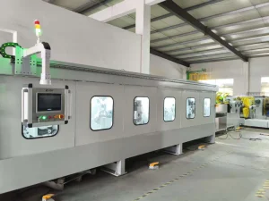
Rectangular wire production involves drawing and/or rolling to obtain the required width, thickness, edge radius, and surface finish. The wire may then undergo enamelling, paper covering, or other insulation processes before winding.
Poor dimensional consistency can create winding and insulation problems. For rectangular wire, roll-gap adjustment, guidance, tension, and lubrication contribute to stable geometry. For foil, strip flatness and edge condition deserve close attention.
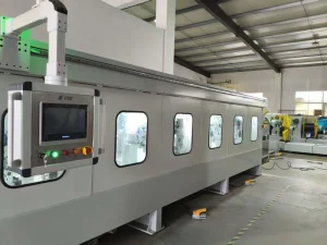
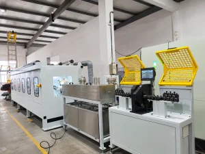
For related upstream processes, see our Copper Rolling Process Guide, precision flat wire rolling mill, and flat magnet wire production line guide.
8. Choosing the Right Winding Design
Begin with rated power, voltage levels, winding current, impedance, permitted losses, cooling method, and available space. Compare foil and rectangular wire designs against the same electrical, thermal, mechanical, and cost requirements.
Request calculations for DC and additional losses, temperature rise, insulation clearances, and short-circuit forces. Also review material availability, winding equipment, production repeatability, repair considerations, and total manufacturing cost.
A foil solution may be attractive for certain low-voltage, high-current designs. Rectangular wire may offer greater flexibility where conductor arrangement, winding geometry, or existing production capabilities favor individually insulated wires. The transformer designer should make the final selection.
9. Quality Checks Before Production Approval
Specify measurable acceptance criteria for conductor dimensions, surface quality, edges, insulation, winding geometry, and electrical connections. For foil, verify strip alignment, insulation placement, and any required joints. For rectangular wire, check width, thickness, corner radius, and insulation integrity.
Agree on representative samples, inspection methods, and documented factory acceptance criteria before production. The goal is consistent, repeatable quality rather than one acceptable trial winding.
Frequently Asked Questions
Are copper foil windings always more efficient?
No. Efficiency depends on conductor dimensions, winding geometry, leakage flux, cooling, and loading. Both designs require loss calculations.
Are copper foil windings only used on the low-voltage side?
They are common in low-voltage, high-current applications, but actual use depends on the transformer’s design and insulation requirements.
Can a flat-wire rolling mill manufacture complete foil windings?
No. A flat-wire rolling mill produces shaped wire for upstream applications. Complete foil windings require suitable copper strip, dedicated winding equipment, insulation handling, and connections.
Conclusion
Copper foil windings and rectangular wire windings can both serve distribution transformers effectively. Their advantages depend on the specific electrical, thermal, mechanical, and manufacturing requirements. Selecting the appropriate design requires engineering calculations and validated production quality.
Sky Bluer Environmental Technology Co., Ltd. (CRM) manufactures precision rolling mills and customized equipment for rectangular copper and other metal wires. Share your material grade, input dimensions, target width and thickness, tolerances, and capacity requirements to discuss an upstream rectangular-wire forming solution.