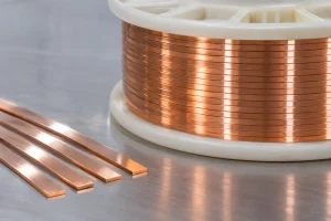
Power transformer windings must carry high currents while controlling losses, temperature rise, and mechanical stress. Two options are conventional rectangular conductors and continuously transposed conductors (CTC). Both can use precision-formed copper, but their construction and winding behavior differ.
Selection depends on winding current, leakage flux, insulation, manufacturing complexity, and total transformer cost. Neither design is universally superior. In particular, the conductor should be assessed as part of the complete winding, because a favorable strand arrangement cannot compensate for an unsuitable cooling or insulation design.
1. What Is a Conventional Rectangular Conductor?
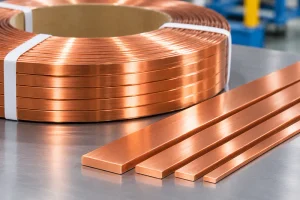
A conventional rectangular conductor is a solid copper wire or strip with a rectangular cross-section, supplied with enamel, paper, or other specified insulation. Its flat surfaces support compact, predictable winding geometry.
Higher-current windings may use parallel rectangular conductors. These can occupy different positions in the leakage field; without suitable transposition or other measures, unequal induced voltages may drive circulating currents between parallel paths.
Conventional rectangular conductors offer straightforward manufacture, handling, and termination when winding requirements do not justify a more complex construction. They may also be specified in copper or aluminum, depending on the transformer design and material requirements. Parallel rectangular conductors can be transposed at selected positions in a winding; they should not automatically be treated as untransposed.
2. What Are Continuously Transposed Conductors?
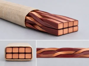
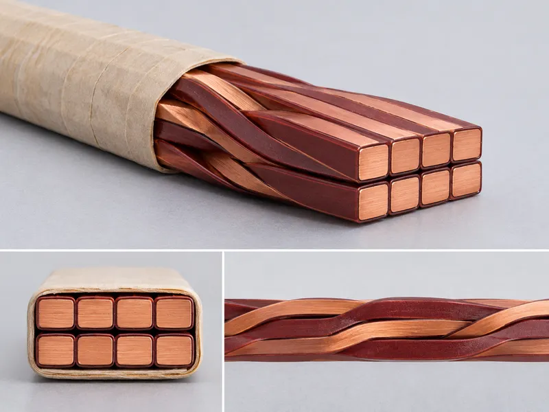
Continuously transposed conductors comprise multiple, individually insulated rectangular strands. Arranged in two adjacent stacks, the strands progressively exchange positions along the conductor length. The result is a multi-strand assembly with a defined overall shape.
Each strand typically has enamel insulation to prevent direct contact with neighboring strands. The assembly may receive external paper insulation or another covering; some designs include bonding features for mechanical stability.
Repeated changes in strand position expose individual strands to more comparable magnetic conditions over the winding length, helping reduce induced-voltage differences and circulating-current losses. Transposition pitch, strand count, and individual strand dimensions must therefore be coordinated with the winding design. The assembly is not merely a bundle of insulated wires.
3. Electrical Losses: Why Transposition Matters
Winding losses include DC resistance losses and additional losses from alternating magnetic fields. Leakage flux can induce eddy currents within conductors and circulating currents between parallel paths, depending on dimensions, position, field distribution, and operating conditions.
A large solid rectangular conductor may have higher eddy-current losses than one divided into insulated smaller strands. Subdivision limits eddy-current loops; transposition also helps equalize induced voltages between parallel strands.
CTC does not eliminate all additional losses. Designers should compare calculated losses and thermal performance for the actual winding geometry and duty cycle rather than relying on conductor type alone. This distinction matters when assessing transformer efficiency: a lower winding loss may be valuable over decades of operation, but only if the reduction is meaningful under the expected loading profile.
4. Insulation, Thermal Performance, and Mechanical Design
Insulation matters in both designs. Conventional wire may use enamel or paper according to dielectric requirements. In CTC, damage to individual strand insulation can create unintended connections and disrupt current distribution.
CTC construction affects flexibility, bending, and packing density. Overall dimensions, insulation build, corner geometry, and winding method must be evaluated together. CTC is not automatically smaller or easier to wind.
Thermal performance also depends on cooling ducts, insulation thickness, oil circulation, hot spots, and winding arrangement. Short-circuit forces and mechanical support matter, especially in large transformers. The conductor must also withstand winding operations without damaging its insulation or distorting the specified profile.
5. CTC vs Conventional Rectangular Conductors: Key Differences
| Evaluation factor | Conventional rectangular conductor | Continuously transposed conductor (CTC) |
|---|---|---|
| Construction | One rectangular wire, or separate parallel wires | Multiple insulated rectangular strands in a transposed assembly |
| Current distribution | Depends on conductor arrangement and any transposition measures | Strand positions are exchanged repeatedly along the length |
| Additional AC losses | May increase with large cross-sections or parallel paths | Can reduce strand eddy-current and circulating-current losses when properly designed |
| Insulation | Enamel, paper, or specified covering | Individual strand insulation; optional outer covering |
| Manufacturing | Generally fewer processing and assembly stages | Requires accurate strand preparation and controlled transposition |
| Cost and selection | Often simpler for suitable winding designs | Added manufacturing cost may be justified in demanding applications |
These are general tendencies. Actual results require transformer-specific electromagnetic, thermal, and mechanical assessment.

6. How Manufacturing Requirements Differ
Both types require accurate rectangular wire geometry. Upstream drawing and/or rolling establishes width, thickness, edge radius, and surface condition. Material selection, reduction, roll-gap control, tension, and lubrication affect consistency.
Conventional wire proceeds to insulation and winding preparation. For CTC, each strand must meet dimensional and surface requirements and receive individual insulation before assembly and transposition. External covering may follow.
Inconsistent dimensions, sharp edges, surface defects, or damaged enamel can cause problems during transposition and winding. Upstream rolling quality therefore matters even for multi-strand assemblies.
For background, see our Copper Rolling Process Guide, precision flat wire rolling mill, and flat magnet wire production line guide.
7. Choosing the Right Conductor for a Transformer Project
Start with winding design: rated current, voltage, leakage-flux distribution, loss limits, cooling, and space. Compare a solid conductor, suitably transposed parallel wires, and CTC for the application.
Compare specifications, insulation, inspection, delivery, and total installed cost. For CTC, specify strand count, individual dimensions, transposition pitch, overall size, insulation, and acceptance criteria. For conventional wire, define cross-section, edge radius, surface, and covering. Ask the transformer design team to quantify the expected loss benefit before accepting the extra complexity and cost of CTC.
8. Quality Checks Before Production Approval
Set measurable acceptance criteria: width, thickness, edge geometry, surface condition, insulation integrity, overall dimensions, and traceability. For CTC, also check strand arrangement, transposition consistency, and specified bonding or outer covering.
For factory acceptance testing, agree on representative sizes, sampling, measurements, and documented results. Require repeatability, not just one acceptable sample. Where applicable, include insulation testing and visual inspection after forming or handling. Acceptance criteria should be agreed before production rather than negotiated after a failed trial.
Frequently Asked Questions
Is CTC always better than conventional rectangular copper wire?
No. CTC can offer loss-related advantages in demanding high-current windings, but its value depends on the electromagnetic design, manufacturing cost, and operating requirements.
Does CTC eliminate circulating-current losses?
No. Transposition helps reduce imbalances in induced voltage between strands, but actual losses depend on the winding design and how effectively the strands are transposed.
Can a flat-wire rolling mill manufacture complete CTC?
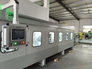
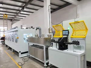
A flat-wire rolling mill produces the rectangular strands used upstream. Complete CTC manufacture also requires strand insulation, specialized transposition equipment, and any specified external covering.
Conclusion
Both conductor types have roles in power transformers. CTC can help manage additional winding losses, while conventional rectangular wire suits many designs. Selection requires electrical, thermal, mechanical, and economic evaluation. Regardless of the final conductor format, consistent strand geometry and surface quality remain essential to reliable downstream processing.
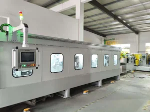
Sky Bluer Environmental Technology Co., Ltd. (CRM) manufactures precision rolling mills and customized equipment for rectangular copper and other metal wires. Share your material grade, input size, target dimensions, tolerances, and production goals to discuss an upstream wire-forming solution.