Introduction
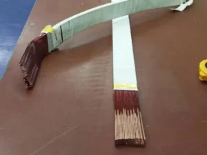
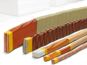
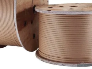
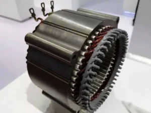
Continuously Transposed Conductors (CTC) are specialized winding conductors widely used in large power transformers and other high-current electrical equipment. Unlike a conventional single rectangular conductor, a CTC conductor is composed of multiple individually insulated rectangular copper strands that are continuously transposed and assembled into one conductor.
The purpose of this structure is not simply to increase conductor size. Transposition helps control current distribution among individual strands and can reduce losses associated with circulating currents and eddy currents in large transformer windings.
For manufacturers, CTC production also places strict requirements on the individual rectangular copper strands. Width, thickness, corner radius, surface quality, insulation consistency, and dimensional tolerance must be controlled before the strands enter the transposition process.
This article focuses on the structure, technical requirements, applications, benefits, and upstream manufacturing considerations of CTC conductors for power transformers.
What Is a CTC Conductor?
CTC stands for Continuously Transposed Conductor.
Instead of using one large solid rectangular copper conductor, CTC divides the required conductor cross-section into multiple smaller rectangular strands.
Each strand is normally electrically insulated before the strands are continuously transposed into the final conductor assembly.
A simplified structure is:
Copper Rod → Rectangular Copper Strands → Strand Insulation → Continuous Transposition → CTC Assembly → Outer Insulation
Typical CTC conductor characteristics include:
| Parameter | Typical Description |
| Conductor material | High-conductivity copper |
| Individual strand shape | Rectangular |
| Strand insulation | Enamel or specified insulation |
| Number of strands | Multiple, application dependent |
| Transposition | Continuous |
| Final conductor shape | Rectangular assembled conductor |
| Main application | Power transformer windings |
| Outer insulation | Paper or specified insulation system |
| Dimensional tolerance | Application dependent |
| Surface requirement | Smooth and defect-free |
The exact number and dimensions of strands depend on transformer design, current requirements, winding geometry, cooling requirements, and electrical loss calculations.
Structure of a Continuously Transposed Conductor
A CTC conductor contains several functional layers.
Individual Copper Strands
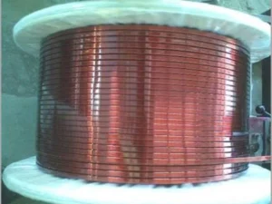
The basic element is a precision rectangular copper wire.
Each strand must maintain stable:
- Width
- Thickness
- Corner radius
- Surface condition
- Mechanical properties
The quality of these individual strands directly affects the stability of the final transposed conductor.
For a detailed introduction to the base conductor, see Bare Rectangular Copper Wire: Types, Applications and Manufacturing.
Strand Insulation
Individual strands are electrically insulated from each other.
This insulation helps restrict unwanted current circulation between strands.
Transposed Structure
The insulated strands periodically exchange their relative positions within the conductor assembly.
This continuous transposition is the defining feature of CTC.
Outer Insulation
After transposition, the complete conductor may receive additional insulation according to the transformer winding design.
Why Are Conductors Transposed?
When a large conductor operates in a changing magnetic field, current distribution within the conductor may become non-uniform.
This can contribute to additional electrical losses.
Instead of using one large solid conductor, engineers can divide the conductor into smaller insulated strands.
However, simply placing several strands together does not automatically ensure that every strand experiences the same electromagnetic conditions.
This is where transposition becomes important.
By continuously changing the relative position of each strand, CTC helps equalize the electromagnetic environment experienced by the strands along the conductor length.
The principle can be summarized as:
Large Conductor → Divide into Smaller Strands → Insulate Strands → Transpose Positions → Improve Current Distribution
CTC vs. Conventional Rectangular Copper Conductors
CTC and conventional rectangular copper wire are both used in transformer winding systems, but their structures are fundamentally different.
| Feature | Single Rectangular Conductor | CTC Conductor |
| Structure | One copper conductor | Multiple copper strands |
| Strand insulation | Not applicable | Individual insulation |
| Transposition | No | Yes |
| Current distribution | Single conductor | Distributed among strands |
| Manufacturing complexity | Lower | Higher |
| Dimensional control | Important | Very important |
| Typical application | General transformer winding | Large power transformer winding |
| Loss optimization | Limited by conductor geometry | Improved through strand design |
The choice depends on transformer capacity, winding design, conductor current, electromagnetic conditions, and engineering requirements.
Typical CTC Strand Specifications
The individual strands used for CTC are generally precision rectangular copper conductors.
Typical engineering ranges may include:
| Parameter | Typical Reference Range |
| Material | Cu-ETP / OF Copper |
| Strand width | Approx. 2–12 mm |
| Strand thickness | Approx. 0.8–3.5 mm |
| Width tolerance | ±0.01–0.03 mm |
| Thickness tolerance | ±0.005–0.02 mm |
| Corner radius | Application dependent |
| Copper condition | Soft / annealed |
| Surface | Smooth and defect-free |
| Conductivity | High-conductivity copper |
| Insulation | Enamel / specified coating |
These values are general engineering references rather than universal CTC standards.
Actual strand dimensions should follow the conductor drawing and transformer manufacturer’s requirements.
Why Strand Dimensional Accuracy Matters
A CTC conductor may contain many individual rectangular strands.
This means that a dimensional error in one strand can influence the assembled conductor geometry.
For example, consider the effect of thickness variation:
| Thickness Variation per Strand | 10 Strands | 20 Strands | 40 Strands |
| 0.002 mm | 0.02 mm | 0.04 mm | 0.08 mm |
| 0.005 mm | 0.05 mm | 0.10 mm | 0.20 mm |
| 0.010 mm | 0.10 mm | 0.20 mm | 0.40 mm |
This is a simplified dimensional example, but it illustrates why consistent strand geometry is important before transposition.
CTC manufacturers should therefore focus not only on average strand dimensions but also on dimensional stability throughout continuous production.
Corner Radius and Edge Quality of CTC Strands
The individual copper strands undergo several downstream operations, including insulation and mechanical transposition.
For this reason, corner geometry must be carefully controlled.
Potential problems include:
| Strand Defect | Possible Effect |
| Sharp corner | Increased insulation stress |
| Burr | Possible insulation damage |
| Uneven radius | Irregular strand geometry |
| Edge crack | Reduced mechanical reliability |
| Surface scratch | Affects insulation quality |
| Dimensional asymmetry | Unstable transposition |
A stable corner radius provides a more consistent base for strand insulation and subsequent transposition.
The target radius depends on strand dimensions and the conductor specification rather than one universal value.
Manufacturing Process of CTC Strands
Before transposition begins, the individual rectangular copper strands must first be manufactured.
A typical upstream process is:
Copper Rod → Wire Drawing → Annealing → Precision Rolling → Sizing → Online Measurement → Surface Inspection → Strand Insulation
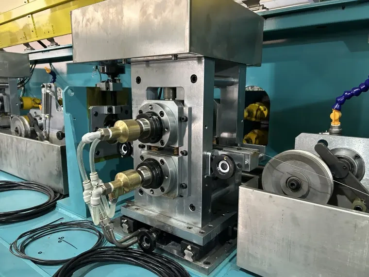
Precision rolling is one of the critical stages.
The rolling process determines:
- Strand width
- Strand thickness
- Corner geometry
- Surface condition
- Dimensional consistency
Typical rolling parameters include:
| Rolling Parameter | Main Influence |
| Roll gap | Strand thickness |
| Roll geometry | Cross-sectional profile |
| Roll alignment | Symmetry |
| Rolling reduction | Material deformation |
| Entry tension | Process stability |
| Exit tension | Dimensional consistency |
| Roll surface quality | Strand surface |
| Online measurement | Dimensional control |
For more information about rolling technology for this type of conductor, see Precision Rolling Technology for CTC, Busbar, and Rectangular Wire Applications.
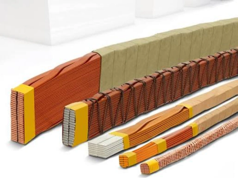
From Rectangular Strand to CTC Conductor
After the individual strands have been manufactured and insulated, they enter the transposition process.
A simplified CTC manufacturing route is:
Precision Rectangular Strands → Individual Strand Insulation → Strand Arrangement →Continuous Transposition → Conductor Compaction / Forming → Outer Insulation → Finished CTC Conductor
The transposition equipment must coordinate the movement of multiple strands without damaging the individual insulation layers.
Important process factors include:
- Strand tension
- Transposition pitch
- Strand alignment
- Insulation protection
- Conductor dimensions
- Line speed
- Final take-up tension
Because multiple strands are processed simultaneously, production stability becomes especially important.
CTC Strand Insulation Requirements
The insulation between individual strands is a fundamental part of the CTC structure.
The insulation system should maintain electrical separation while also tolerating mechanical movement during transposition.
Important considerations include:
| Requirement | Purpose |
| Uniform insulation | Stable electrical separation |
| Good adhesion | Prevent coating damage |
| Controlled thickness | Maintain conductor dimensions |
| Smooth surface | Support transposition |
| Mechanical resistance | Withstand strand movement |
| Thermal compatibility | Meet transformer requirements |
The quality of the bare copper surface before insulation can influence the consistency of the finished strand.
For more information about enamel-insulated rectangular copper conductors, see: What is Enamelled Copper Flat Wire? Applications and Benefits.
Main Benefits of CTC Conductors
CTC technology is mainly used because it provides electrical and manufacturing advantages for large transformer windings.
Reduced Eddy Current Losses
Dividing a large conductor into smaller insulated strands helps reduce the path available for eddy currents within the conductor.
Better Current Distribution
Continuous transposition helps individual strands experience more balanced electromagnetic conditions along the conductor length.
High Copper Cross-Section
Multiple strands can be combined to create a conductor capable of carrying high current while maintaining a manageable individual strand size.
Flexible Winding Design
CTC gives transformer designers more flexibility in selecting conductor dimensions and winding arrangements.
A simplified comparison is:
| Benefit | CTC Design Contribution |
| Lower additional losses | Multiple insulated strands |
| Better current distribution | Continuous transposition |
| High current capacity | Multiple copper strands |
| Controlled conductor geometry | Precision strand production |
| Transformer efficiency | Optimized winding conductor |
Applications of CTC Conductors
CTC is primarily associated with medium- and large-capacity transformer windings.
Typical applications include:
- Power transformers
- Generator step-up transformers
- Grid transformers
- Large distribution transformers
- High-current transformer windings
- Specialized electrical equipment
CTC is especially useful where a single large conductor would create undesirable electromagnetic losses or become difficult to optimize within the winding design.
For general transformer conductor production technology, see: Precision Flat Wire Rolling Mills for Transformer Copper and Aluminum Conductors.
CTC vs. Paper Covered Copper Flat Wire
CTC should not be confused with conventional paper covered rectangular copper wire.
| Feature | Paper Covered Flat Wire | CTC |
| Copper structure | Single conductor | Multiple strands |
| Individual strand insulation | No | Yes |
| Continuous transposition | No | Yes |
| Outer paper insulation | Common | Can be applied |
| Manufacturing complexity | Moderate | High |
| Typical application | Transformer winding | Large transformer winding |
A paper covered conductor can be produced by wrapping insulation around one rectangular copper conductor.
CTC requires additional strand production, insulation, transposition, and final conductor assembly.
For conventional paper-covered conductor technology, see: Paper Covered Copper Flat Wire for Transformer Windings
Quality Control in CTC Production
Because CTC contains multiple precision strands, quality control should cover both the individual strand and the final assembled conductor.
Individual Strand Inspection
Typical inspection items include:
- Width
- Thickness
- Corner radius
- Surface quality
- Insulation thickness
- Electrical properties
- Mechanical condition
Finished CTC Inspection
Typical parameters include:
| Inspection Item | Purpose |
| Overall width | Verify final conductor geometry |
| Overall thickness | Control winding dimensions |
| Transposition pitch | Verify strand arrangement |
| Strand insulation | Ensure electrical separation |
| Surface condition | Detect mechanical damage |
| Conductor straightness | Support winding |
| Take-up quality | Protect finished conductor |
Online monitoring can help detect deviations before large quantities of material are produced.
Production Equipment Requirements
A complete CTC manufacturing system involves more than a transposition machine.
Depending on the customer’s production scope, equipment may include:
Copper Wire Drawing → Annealing → Precision Rolling → Online Measurement → Strand Insulation → CTC Transposition → Outer Insulation → Take-Up
For the rectangular strand production section, important equipment features include:
- Precision rolling mills
- Accurate roll-gap adjustment
- Controlled corner radius
- Online width and thickness measurement
- Stable tension control
- Surface protection
- Precision winding
For an introduction to integrated CTC equipment and upstream conductor preparation, see: CTC Production Line.
Information Required for a CTC Strand Production Solution
Before selecting equipment for CTC conductor manufacturing, customers should define both the individual strand and final conductor requirements.
| Required Information | Example |
| Copper grade | C11000 / OF Copper |
| Raw material diameter | mm |
| Strand width | mm |
| Strand thickness | mm |
| Width tolerance | ±mm |
| Thickness tolerance | ±mm |
| Corner radius | R mm |
| Number of strands | Customer specified |
| Strand insulation | Enamel / Other |
| Transposition pitch | Customer specified |
| Final CTC dimensions | mm |
| Production speed | m/min |
| Coil weight | kg |
| Online measurement | Required / Optional |
These parameters allow the production process to be designed around the final transformer conductor rather than only the nominal strand size.
Conclusion
Continuously Transposed Conductors are an important conductor technology for large power transformer windings.
By dividing a large copper conductor into multiple individually insulated rectangular strands and continuously transposing their positions, CTC can help improve current distribution and reduce additional losses associated with large transformer conductors.
However, the performance of the final CTC begins with the precision of every individual strand.
Manufacturers must carefully control:
- Strand width and thickness
- Dimensional tolerance
- Corner radius
- Surface quality
- Copper mechanical condition
- Strand insulation
- Transposition stability
- Final conductor geometry
Sky Bluer Environmental Technology Co., Ltd. provides precision rolling mills and customized wire production solutions for rectangular copper strands used in transformer, CTC, magnet wire, and other electrical conductor applications.
CRM solutions can integrate wire drawing, annealing, precision rolling, online dimensional measurement, tension control, and precision take-up according to the customer’s conductor requirements.
For manufacturers planning a CTC or rectangular copper strand production project, providing the raw material diameter, strand dimensions, tolerances, corner radius, number of strands, insulation requirements, production speed, and coil specifications will help our engineering team determine the appropriate production solution.