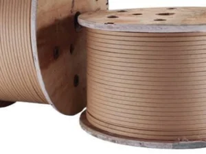
In rectangular copper wire production, meeting width and thickness tolerances is not enough. A conductor can measure correctly across its flat surfaces yet have corners that are too sharp, excessively rounded, or inconsistent from one side to the other.
These defects can affect insulation, copper area, and downstream forming for transformer and motor conductors.
Reliable control requires a defined profile, suitable tooling, stable rolling, and direct inspection—not repeated roll-gap adjustments.
What Is Edge Radius in Rectangular Copper Wire?
Edge radius—more precisely, corner radius—is the curved transition between two adjacent faces of a rectangular conductor. A drawing may specify R0.30 mm, together with an acceptance tolerance and, where necessary, a defined profile shape.
Natural rounding during flattening does not necessarily produce a circular arc. All four corners should be checked, even when width and thickness meet tolerance.
For an ideal conductor with four identical circular corner radii, copper cross-sectional area is:
A = wt − (4 − π)R²
Here, w is overall width, t is overall thickness, and R is corner radius, all in millimeters. The equation excludes irregular or chamfered edges and shows how radius changes copper area.
For an overview of conductor dimensions and production routes, see Bare Rectangular Copper Wire: Types, Applications and Manufacturing.

Why Corner Radius Matters in Electrical Conductors
Insulation performance. Sharp corners, burrs, and abrupt profile transitions can increase the risk of damaging enamel or insulation paper during coating, wrapping, and winding. Rounding helps, but insulation performance still requires testing.
Winding geometry. Unequal corners can affect how insulated conductors fit together, particularly in closely packed transformer windings and formed motor conductors. A controlled radius helps maintain a repeatable cross-section through later processing.
Electrical design. Excessive rounding reduces copper area within a fixed width-and-thickness envelope. Engineers should assess the actual cross-section when conductor resistance or packing calculations are sensitive to geometry.
These considerations matter before paper covering copper wire for transformer windings.
How Edge Radius Forms During Precision Rolling
A typical production route is:
Round Copper Wire → Drawing → Flat Rolling → Edge Forming → Final Sizing → Inspection → Take-Up
Annealing may be included at a suitable point to achieve the required mechanical condition. The sequence depends on the product specification.
During initial flattening, rotating rolls reduce thickness while copper flows longitudinally and laterally. Intermediate passes develop width and thickness. Where a defined radius is required, dedicated edge-forming tooling shapes the corners before final sizing.
| Production Stage | Primary Function | Radius-Control Priority |
|---|---|---|
| Initial flattening | Transform round wire into a flat profile | Avoid uncontrolled lateral spreading |
| Intermediate rolling | Develop width and thickness | Maintain symmetric deformation |
| Edge forming | Create the specified corner profile | Match tooling to conductor geometry |
| Final sizing | Stabilize finished dimensions | Preserve the formed corners |
The critical distinction: adjusting a conventional roll gap mainly changes thickness. It cannot reliably correct an incorrect corner profile if the forming tooling, wire position, or deformation schedule is the real cause.
Five Factors That Determine Corner Radius Consistency
Roll Profile and Alignment
Worn profiles, misalignment, runout, or damaged roll surfaces can produce asymmetric corners. A nominal radius machined into a tool is not automatically identical to the finished radius because metal flow and elastic recovery also influence the result.
Reduction per Pass
Heavy reductions can increase lateral spreading and distort an already formed corner. Select reductions based on input size, copper condition, tooling, and target geometry; the final pass cannot reliably correct unstable upstream deformation.
Copper Grade and Mechanical Condition
Electrical conductor grades include Cu-ETP (C11000) and oxygen-free copper such as C10200. Annealed and work-hardened copper respond differently to rolling loads. Variations in incoming hardness can change the corner profile.
Tension and Wire Guidance
Unstable entry or exit tension can affect rolling conditions and dimensional repeatability. Poor centering may load the two edges differently, producing unequal corner radii. Check guides, tracking, and drive synchronization first.
Lubrication, Temperature, and Tool Wear
Friction and roll temperature influence material flow. Inconsistent lubrication, contamination, or progressive wear can cause radius drift during a long production run. Keep tooling clean and inspect it regularly.
A Practical Method for Controlling Edge Radius
1. Start with a complete drawing. Confirm copper grade, incoming diameter, finished width and thickness, corner radius and tolerance, surface requirements, and downstream insulation or forming process. Specify whether all four corners must meet the same radius requirement.
2. Validate the forming setup. Check tool profiles, alignment, wire centering, and the sequence of rolling and edge-forming operations. Produce trial material at representative operating conditions. Measure samples after the stage most likely to generate the defect, not only at the take-up.
3. Change one cause at a time. If opposite corners differ, investigate centering and alignment first. If all corners are too large, check tooling and reduction conditions. Record the adjustment, the resulting profile, and the stable production settings.
4. Verify repeatability. Inspect samples at startup, after tooling changes, and during sustained operation. Include the beginning and end of trial coils where practical. Acceptance should cover corner geometry, width, thickness, surface condition, and consistency along the wire length.
Measuring Corner Radius and Verifying Quality
A width/thickness laser gauge is useful for detecting dimensional drift, but it does not establish the corner radius by itself. Radius measurement requires access to the actual cross-sectional contour.
Suitable methods include calibrated optical microscopy, a profile projector, or an optical profile measurement system. For a nominally circular corner, the inspection procedure should specify which contour points are used for radius fitting and how the transition into the flat surfaces is evaluated. Avoid distorting soft copper during sample preparation.
Inline profile measurement may be considered where the sensing system can resolve the corner geometry. A closed-loop radius correction system additionally needs a controllable edge-forming mechanism; automatic width and thickness adjustment alone is not equivalent to automatic radius control.
Use the applicable product standard and customer drawing; tolerances vary by conductor type.
Common Edge Radius Problems and Solutions
| Observed Problem | Likely Cause to Check | Practical Response |
|---|---|---|
| All corners too sharp | Insufficient edge forming or incorrect tool profile | Verify forming-tool geometry and engagement |
| Radius too large | Excessive edge deformation or unsuitable tooling | Review forming profile and pass schedule |
| Left/right corners differ | Off-center feeding or roll misalignment | Recenter wire and check roll alignment |
| Radius changes along the coil | Tension variation, material inconsistency, or tool heating | Trend process conditions and inspect incoming wire |
| Burrs or rolled-over edges | Damaged tooling or excessive local deformation | Inspect contact surfaces and revise forming conditions |
| Scratches near corners | Worn guides or contaminated rolls | Clean or replace affected components |
Increasing rolling pressure indiscriminately can worsen other corners or surface quality.
Choosing a Rolling Mill for Controlled Corner Radius
A conventional 2-Hi mill is effective for flattening, but a specified radius may require a dedicated edge-rounding stage. Multi-roll or profiled forming equipment can also be considered where the conductor geometry justifies it. Select equipment by finished geometry and verified capability.
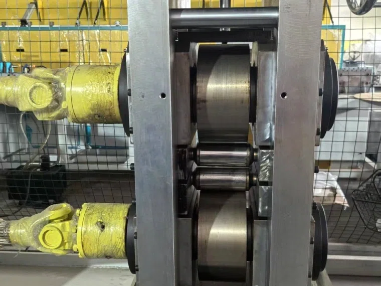
The CRM Precision Flat Wire Rolling Mill for Transformers lists two 2-Hi rolling stands followed by an active edge-rounding mill, together with tension control, lubrication and cooling, dimensional measurement, and take-up equipment.
| Published CRM Parameter | Specification |
|---|---|
| Round wire input diameter | 1.0–6.0 mm |
| Finished width / thickness | 0.6–10 mm / 0.4–6 mm |
| Width / thickness tolerance | ±0.01 mm / ±0.005 mm |
| Adjustable corner radius | R0.05–1.0 mm |
| Design speed | 180 m/min |
These are the manufacturer’s published equipment specifications, not guaranteed simultaneous performance for every conductor size and radius. Actual capability, tolerance, tooling, and production speed should be confirmed against the customer’s material and drawing through technical evaluation or trials.
Frequently Asked Questions
What is the correct edge radius for rectangular copper wire?
There is no universal value. The specified radius depends on conductor dimensions, insulation design, winding requirements, and applicable product standards. Use the customer’s cross-sectional drawing and define an acceptance tolerance rather than selecting a radius from a generic machine range.
Can a 2-Hi rolling mill produce a controlled corner radius?
A standard 2-Hi mill can create naturally rounded edges during flattening. A closely specified circular corner may require profiled tooling or a separate edge-forming operation. Feasibility must be demonstrated for the required dimensions and material condition.
Why are the four corner radii different?
Common causes include wire misalignment, unequal forming contact, worn rolls, and asymmetric material flow. Inspect the conductor position and tooling condition first; a thickness adjustment alone may not resolve the underlying problem.
Can an online laser gauge measure corner radius?
A conventional width/thickness gauge cannot directly measure the full corner profile. Radius verification requires suitable contour measurement, either offline or with an appropriately configured inline system. Automatic correction also requires an adjustable forming stage.
What should I send a rolling mill supplier for evaluation?
Provide copper grade and condition, input diameter, finished width and thickness, tolerances, required radius, cross-sectional drawing, production capacity, and take-up requirements. State whether the wire will be enameled, paper covered, or formed after rolling.
Conclusion
Consistent edge radius is the result of controlled metal flow, suitable forming geometry, stable production conditions, and reliable profile inspection. Width and thickness measurements remain essential, but they cannot substitute for direct verification of the four corners.
Sky Bluer Environmental Technology Co., Ltd. supplies CRM precision rolling equipment for copper and aluminum conductors. For a rectangular copper wire project, share your material, input dimensions, finished profile drawing, corner radius, tolerances, and required output so the engineering team can assess an appropriate rolling configuration.